[Logo] Argo Navis Users' Group
  [Search] Search   [Recent Topics] Recent Topics   [Hottest Topics] Hottest Topics   [Top Downloads] Top Downloads   [Groups] Back to home page 
[Register] Register /  [Login] Login 
Messages posted by: wildcard
Forum Index » Profile for wildcard » Messages posted by wildcard
Message
Hi Massimo,

Your ISP is bouncing our email replies to you so I have contacted them.

In any case I suspect you don't have a problem after all and that you may just be looking at the rounded numbers that reflect the finite encoder resolution.
Thanks for the post.

You may not be aware that we provide full technical support by direct email or by telephone.
The contact details are here :-
https://www.wildcard-innovations.com.au/contact.html

Please drop us a line and we are here to assist. Some have described our support as the best they have ever received for any product they have ever purchased.

This forum tends to be for broader questions, though is not limited to that.


Hi BC,

Thanks for the question.

Since the pointing data is gathered with respect the arbitrary star alignment, it is not possible to merge two sets of data from two different alignments.

One way to appreciate why that is so is to consider a telescope that has arbitrary geometric pointing errors built into it.
Such a telescope never points at exactly where it is thought to be pointing.

When one does a two star alignment using such a hypothetical telescope, one is effectively declaring - "I solemnly swear that the two points I have just aligned on are free of errors."
Well we know of course that can't be true because there is nothing special about those two points compared to any other and therefore they must be polluted with the same geometric
errors as any other arbitrary two points.

To further exacerbate the issue, the geometric nature of many types of pointing errors is such that they are often a function of the telescope's altitude or azimuth, or possibly some harmonic of that.
In other words, many of these types of errors are not constant across the sky.

When one gathers pointing data, it therefore is built upon the scaffolding of the arbitrary two-star alignment. This is why one should never save the index error terms because they
effectively null out the finite errors of the arbitrary alignment, This is also the reason the data from two different alignments would be a challenging thing to merge.

This is a long-winded way of saying that the workaround is to indeed not power off the system and to use the same star alignment.
But I hope the above background might give you some insight as to why that is so rather than leave one thinking it is through want of functionality.

Attached is a PowerPoint presentation by Argo Navis user Scott Tannehill who contributed this document in June 2007.

Scott illustrates a procedure for centering your altitude encoder.
Hi Rick,

I trust you received my email response yesterday?

It's a Panasonic CR1220 3V or equivalent. We use the equivalent one from Renata ourselves.

The 12 code refers to the fact the battery is 12.5mm in diameter. The 20 refers to it being 2.0mm in height.

Duracell will refer to it as a DL1220
Energizer as a ECR1220
Maxell and Sony both refer to it as a CR1220.

For example, see https://www.digikey.com/en/products/filter/batteries-non-rechargeable-primary/90?s=N4IgTCBcDaIMICUC0BGMYAMIC6BfIA

See "Appendix F - How to replace the Lithium coin cell battery" of the User Manual pages 233-235
https://www.wildcard-innovations.com.au/documentation.html
Hi Jerry,

Indeed the ability to sample multiple TPAS coordinates through the FROM PLANETARIUM interface is not supported.

In theory, one could sample the same object multiple times as its apparent position changed due to Earth rotation and this would make for valid TPAS data.
We rolled a one-off custom special version of the firmware for a solar observatory research institution in Hong Kong a few years back that provided for that.
This particular observatory just operated during the day and just looked at the Sun, so that was the only object they could sample.

However, in the design of TPAS we had a couple of major requirements. One was that it be able to help provide improved pointing via a pointing model and the second
was that it could be easily operated via an interface using just one thumb.

When the user is sampling an object, we made the design decision that should they re-sample the same object it was most likely because they weren't entirely happy
with the object being centred or possibly because they had originally misidentified it. This behaviour was also consistent with that of MODE ALIGN STAR and MODE ALIGN.
If you align on an object you already had aligned on, it simply updated that alignment point rather than create a second one.

So we purposely designed the behaviour to be that the system would only hold a single sample associated with a single unique internally referenced name.

By doing that we also thought it made the REVIEW DATA menu easier to use, You could see the name of the object you had sampled and if there was only one instance of it, there
would be no ambiguity as to which entry you might want to keep and which you might have wanted to delete.

Since the FROM PLANETARIUM pseudo catalog entry only provides a single internal reference (that is it is the "FROM PLANETARIUM" object) with no name,
the behavior is that when a new set of coordinates are sent to it, it still internally is regarded as the same object as far as TPAS is concerned.

So that provides the historical design decision background as to why the ability to use the FROM PLANETARIUM catalog entry for sampling multiple TPAS objects is not supported.

Hi Charlie,

Seasons Greetings!

Is this the affable Charlie Warren of Amateur Astronomy Magazine who was down here for the OzSky event in 2009?

I hope you have been keeping well. smilie

cbwarren wrote:My issue might simply be the connection. I am using a standard data cable to serial adapter.


In all probability, that will be your problem.

There is no such thing as a "standard data cable to serial adapter". There is no industry standard.

The RJ socket pinouts on the Argo Navis serial port and the set of connections inside the D-connector are custom designed by us.
They were carefully chosen to mininize the chance of damage should a user accidentally plug a serial cable into an encoder port.

Though serial cables for other devices may look similar, chances of them being wired the same way are small.
There are something like 24 different permutations on the RJ plug alone. Then the RJ plugs at either end can be wired in two different orientations.
Then the multiplicity of possible connections from the RJ socket at the back of the D-connector to the D-connector pins makes the chance of plugging in
some arbitrary cable and it working impossibly slim.

In fact one has to be careful. If one uses the wrong serial cable, it can cause a short, possibly damaging the unit and/or PC.

What you want to make sure you have is the genuine Argo Navis Serial Cable :-
https://www.wildcard-innovations.com.au/ser_cbl_describe.html

These can be ordered online from here :-
https://www.wildcard-innovations.com.au/purchase.html

If you need frther assistance, please don't hesitate to contact us at sales@wildcard-innovations.com.au


In this thread we attempt to post some tips on performing an alignment

Alignment object queue
Argo Navis maintains a queue of alignment objects and by default its alignment is based on the last object you aligned on and the one previous to that.

There is a SETUP menu called SETUP ALIGN PICK which can change the depth of that queue, but we recommend to keep that setting at its default value of
ALIGN PICK=LAST+
PICK 1 OF 1 PREV

The SETUP ALIGN PICK menu is deprecated in favour of more advanced functionality, in particular the Telescope Pointing Analysis System (TPAS) which is controlled from within the SETUP MNT ERRORS menu.

Altitude reference
Telescopes are fitted with incremental encoders and these have no inherent zero reference point when they are powered on.
As it transpires, one only needs to define the altitude reference point. This is the job of the FIX ALT REF menu.

Setting the altitude reference point need not be onerous thanks to an Argo Navis feature called AUTO ADJUST ON when you perform the FIX ALT REF step.

To set it up, DIAL up MODE SETUP, SETUP ALT REF and enter a value of +090.000.
Then when you perform the FIX ALT REF STEP, DIAL up ALT REF=+090.000 AUTO ADJUST ON.

Perform your two star alignment as normal. The WARP factor should then be 0.00 (A) where the (A) indicates the ALT REF point was automatically adjusted.
If you see a non-zero WARP factor when AUTO ADJUST is ON or an (X) instead of an (A), it means something is amiss, such as a misidentified star or cable not plugged in.

Keep in mind that though a WARP factor of 0.00 is a prerequisite for good pointing performance, it does not necessarily guarantee good performance.
The reason is that the AUTO ADJUST mechanism bends over backwards to correct the ALT REF point so as to produce a WARP factor of zero wherever possible, even if you have misidentified the alignment stars.

The altitude reference point is with respect the mount's own axis and not the local horizontal as defined by gravity.
One common question user's have is, "Do I need to level the mount", to which the answer is "No".

To illustrate the point, the telescope below is resting on sloping ground. Note that the ALT REF 90° angle occurs when the optical axis of the scope is parallel to the mount's own azimuth axis.

image

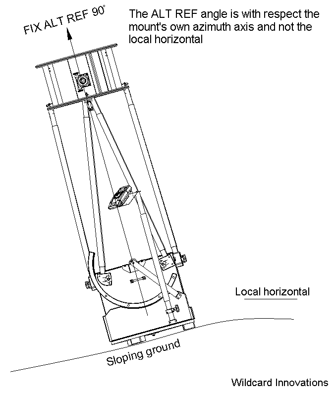
When orienting the OTA using AUTO ADJUST ON, one need only provide the roughest of hints as to the actual angle.
For example, if the OTA were angled at only 80° and the ALT REF point was declared as 90°, AUTO ADJUST ON will still converge to the correct result after the two star alignment.
What this typically means in practice on a Dob is to simply push the OTA to point upward until the mirror box hits the back of the rocker box and will go no further and then perform your FIX ALT REF step.
The whole process should take you only a few seconds.

Only two alignment stars are required to define an alignment
Just as two points define a straight line, two stars are sufficient to define a perfect alignment.

Choice of alignment stars
When using AUTO ADJUST ON, the two alignment stars must have different azimuths in order for its magic to work.
That is to say, when you choose a second star, make sure that it entailed the mount moving in azimuth.

The encoders have a finite resolution. A 10,000 step encoder has a resolution of about 2.1 arc minutes per step. Typically the alignment stars will have angular separations
that are way in excess of the finite resolution of the encoders.

Apart from that, there are no other rules in theory that govern the selection of alignment stars.

In practice, all mounts have fabrication errors of varying amounts that can impact on the pointing performance.
In the face of mount errors, the pointing error residuals will tend to be smallest n the vicinity of the two alignment stars.
With that in mind, it can be beneficial to choose one of the alignment stars to be in the vicinity of the area you are about to observe in.

When moving to a new part of the sky, if it is found that the pointing error has become large, one strategy is to either use MODE ALIGN STAR or
perhaps MODE IDENTIFY in combination with MODE ALIGN to align on a new star in that new area.

When doing that, be mindful of maintaining reasonable angular separation between successive alignment stars. The oldest star will be bumped off the queue and
the one previous to that will take its place. So you will again be aligning on the star you just aligned on and the one previous to that.
For AUTO ADJUST ON to do its magic, those two stars require movement of the mount in azimuth.

Time between alignments
After aligning on the first star, there is no pressing urgency to align on the second.
Though the Earth is rotating, Argo Navis is keeping track of relative time and taking that into account.
In fact it is even taking into account the tiny corrections needed for atmospheric refraction.
So after you align on the first star, you could go inside and drink coffee, chat to a friend on the phone and come back an hour late and complete the alignment on the second star without any penalty in accuracy.

Date, time and location
In general, Argo Navis does not require you to have set the date, time and location in order to perform a star alignment.

However, having the date and time set allows Argo Navis to compute the position of solar system objects and it also is used to compute the small corrections for atmospheric fraction when SETUP REFRACTION is switched to ON
and for precession.

Except when observing artificial satellites, the time and location need not be GPS accurate.

The Moon is close enough to the Earth that its position varies appreciably according to your location on Earth. Set the latitude and longitude in SETUP LOCATION to at least those of your nearest city or town.

When using the ServoCAT, Argo Navis computes where the local horizon is based on your time and location. If an object is computed to be beneath the local horizon, then the ServoCAT will not take the slew.
Therefore you should set the date, time zone and time in SETUP DATE/TIME and location in SETUP LOCATION.
Time zones west of Greenwich such as in the Americas are always negative.

Altitude encoder check for Obsession owners
The altitude encoder needs to be mounted at the precise center of rotation.
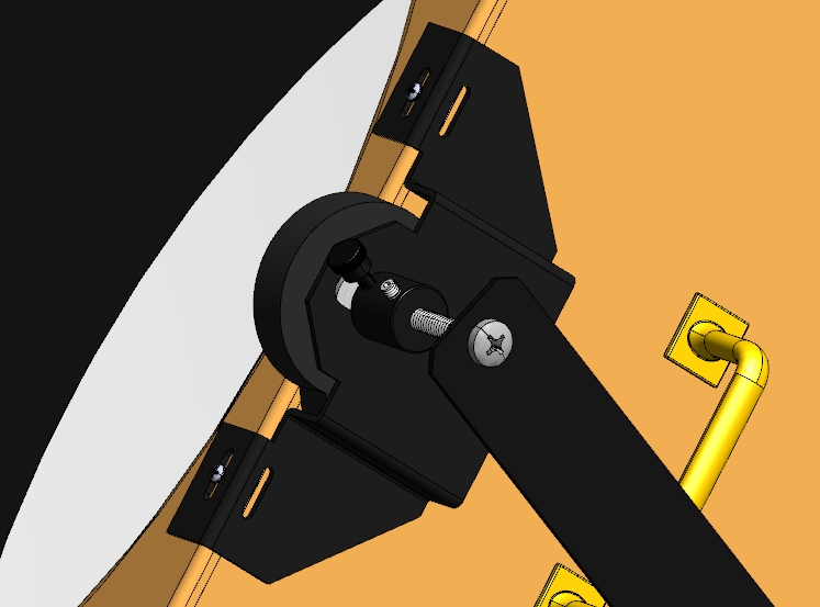
On the Obsessions the encoder is mounted on a bracket, The bracket is attached to either the edge of the mirror box or the cross bar of the altitude trunnion.
This bracket can be adjusted left or right if required by loosening the thread cutting screws that pass through the slots in the bracket. Re-fasten once positioned.
The encoder is held in pace by a hex nut and can be adjusted up or down. The center of rotation by design lies in the plane of the top edge of the mirror box or the top surface of the bar across the altitude trunnion.

The altitude encoder bracket fastened to the top edge of the mirror box like on the 18" Obsession Classic is depicted in the drawing below
image

The importance of the exact centering of the altitude encoder cannot be over-emphasized.
If the encoder is not centered, it will precess around the true altitude axis and this will result in a pointing error residual.

On the Obsessions, the two brass thumbscrews at the far end of the altitude tangent arm should be kept slightly loose as depicted in the drawing below :-
image

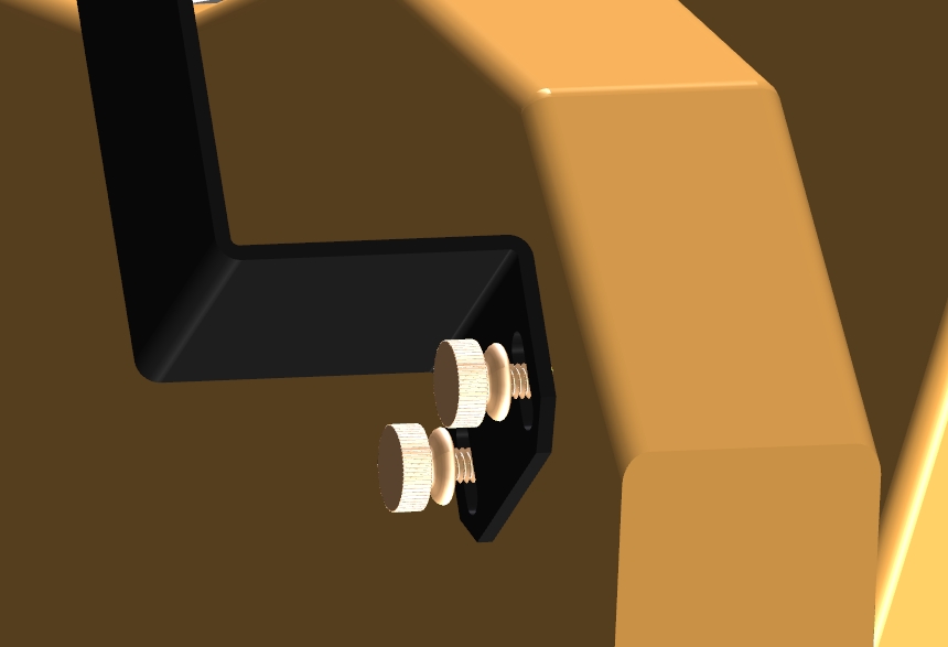
Since the tangent arm is mounted at an angle, gravity will keep it in place so it maintains its reference.
The reason for keeping them loose is because if the encoder is not exactly centered or if the bearing is slightly eccentric, the encoder will precess around the true altitude axis and the
far end of the tangent arm will then want to move radially in or out. If the thumbscrews are tight, then a sideways force will be exerted on the encoder.
The encoders don't "like' sideways force and it can cause them to misread and in the worse case mechanically fail.
Loosening the thumbscrews therefore provides a certain amount of "give".

Myths and misconceptions
Aligning on Polaris is fine. It is just another star in the sky. There is nothing special about it because of its proximity to the celestial pole.

Some users say they will align on a star, then align on a second, then go back and re-align on the first star again in the belief this incantation makes the pointing better.
Whenever you re-align on one of the two alignment stars, the alignment queue is maintained and the information for the star you just aligned on will be updated.
However, doing this is totally unnecessary unless you believe you had not accurately centred the star in the first place.

You probably don't need a reticle eyepiece for alignment. Most of us are pretty good at estimating the center of any plain eyepiece without the need for the cross-hairs of a reticle.
If you have one, by all means feel free to use it. If you don't, a high powered eyepiece is fine.

As discussed above, you don't need to level the mount. Some users mistakenly believe that levelling the mount with a spirit level will improve the alignment. It will not.
Unlike the exaggerated slope in the drawing above, chances are you will setup on reasonably level and flat ground. If the telescope can shift in any way in addition to its altitude and azimuth
motions, it will bring about a random pointing error. If you need a ladder to observe, setting up on level ground makes sense in any case. But it is not a prerequisite for using your Argo Navis.

Mount fabrication errors
For the majority of users, the fabrication errors within the mount are small enough that using AUTO ADJUST ON and a two-star alignment are sufficient.

Ensuring that the altitude encoder is centred and performing what we refer to as the Daytime Encoder Test should be the first port of call for those who are not meeting their pointing performance goal.

See the Argo Navis User Manual pp 123-124 on how to perform the Daytime Encoder Test.
https://www.wildcard-innovations.com.au/documentation.html

Argo Navis has a powerful featured called the Telescope Pointing Analysis System (TPAS).
TPAS provides a means whereby during performing a star pointing test, it can analyse and potentially compensate for some of the more common systematic fabrication errors found within mounts.
For example, see this page for descriptions and animated examples of the pointing error that is induced if the azimuth axis and altitude axis are not precisely at right angles or if the optical axis is not precisely at
right angles with respect the altitude axis :-
https://www.wildcard-innovations.com.au/geometric_mount_errors.html

The Argo Navis User Manual has a comprehensive section describing the use of the Telescope Pointing Analysis System (TPAS). See page 122.
https://www.wildcard-innovations.com.au/documentation.html

A quick tutorial on the use of TPAS appears on this forum here :-
https://www.wildcard-innovations.com.au/forum/posts/list/30.page

Hi Jeff,

Sometimes when users have not used their unit for an extended period, they inadvertently have left AA batteries in there that can leak or vent.
A lot of enthusiasts are dusting off scopes during the COVID crises they haven't used in a while, so they are coming across issues such as leaving batteries in gear, or mirror aluminization, and so on.

You might want to check if there was any indication of a battery having leaked or vented. White residue or staining in the battery compartment, or corrosion on the battery terminals are a tell-tale sign.

If the alkaline material makes it way onto the circuit board, it can etch circuit traces and metal component leads over time.

If the unit does not start in BOOT LOADER mode when fresh AA batteries are installed, it indicates something is seriously amiss.

Email sales@wildcard-innovations.com.au and we can advise on weighing up issuing a Return Material Authorization (RMA) and shipping the unit for inspection
against purchasing a new replacement. How many years of service the unit has already given you may play a part in that decision.
The US Dollar is strong against the Australian Dollar at the moment so a new unit including shipping can be picked up at a bargain price.

But having the current unit inspected is also an option to consider, so drop us that email.
Hi John,

Thanks for the post.

Since an identical thread is on the ServoCAT Group I will just post a link to that there :-
https://groups.io/g/ServoCAT/message/6187
Hi Scott,

Thanks for the post and welcome to the Group! Greetings to you there in Tasmania, one of our favourite parts of the world.

Just a reminder to set 20000 steps on the azimuth axis and leave the default of 10000 on the altitude axis.

As part of your setup, you will need to establish the encoder direction senses which are the +/- signs in SETUP ALT STEPS and SETUP AZ STEPS.

The following is a procedure that helps you establish what they should be. The advantage of this procedure is that you can even perform during the daytime indoors.

To check the SETUP ALT STEPS sign, point the Optical Tube Assembly (OTA)
to the vertical and DIAL up MODE FIX ALT REF, ALT REF=+90, AUTO ADJUST
OFF and then press ENTER. Now DIAL up MODE ENCODER. The right-hand
displayed value should be close to +90 degrees. Now push the OTA
downward in Altitude toward the horizon. The right-hand displayed value
should decrease, +89, +88, ... +3, +2, +1, 0 as you go from the zenith
toward the horizon. If not, reverse the SETUP ALT STEPS sign and repeat
the test.

To check the SETUP AZ STEPS sign, rotate the scope in Az clockwise
whilst observing the left-hand displayed value in MODE ENCODER.
The Az angle should increase. If it does not, reverse the SETUP AZ STEPS sign.

As mentioned in the User Manual, irrespective of which way the
arrows point in GUIDE mode, always push the scope in a direction
that makes the GUIDE angles closer to zero. One can later change the
convention of which way the arrows point using SETUP GUIDE as a
matter of personal preference for your particular installation.

Once you have correctly established the encoder direction senses,
we also recommend you use AUTO ADJUST ON when you perform the FIX
ALT REF step. To set it up, DIAL up MODE SETUP, SETUP ALT REF and
enter a value of +090.000. Then when you perform the FIX ALT REF
STEP, DIAL up ALT REF=+090.000 AUTO ADJUST ON. Perform your two star
alignment as normal. The WARP factor should then be 0.00 (A) where
the (A) indicates the ALT REF point was automatically adjusted. If
you see a non-zero WARP factor when AUTO ADJUST is ON or an (X)
instead of an (A), it means something is amiss, such as a
misidentified star or cable not plugged in. Keep in mind that though
a WARP factor of 0.00 is a prerequisite for good pointing
performance, it does not necessarily guarantee good performance. The
reason is that the AUTO ADJUST mechanism bends over backwards to
correct the ALT REF point so as to produce a WARP factor of zero
wherever possible, even if you have misidentified the alignment
stars.

If you ever need assistance, please don't hesitate to email or to give us a call.
Below are a couple of snapshots I took on Friday 9 October 2020 whilst at the factory that manufactures the Argo Navis units here in Sydney.

Every single Argo Navis ever made was manufactured in Sydney.

We are particularly proud of the fact that the majority of workers involved in its production are woman.
We have always been proud of that but even more so in 2020.

The first snapshot shows racks of Argo Navis printed circuit assemblies.
These particular units have reached the quality assurance (QA) stage of the factory pipeline where they are awaiting testing and inspection.

The wires go to the battery terminals and the pink anti-static bubble-wrap is taped over the displays to protect them during handling.

Once the units are housed into their enclosures, they undergo further inspection and at least 24 hours of continual burn-in testing.

The second snapshot is a view of the testing and packaging area of the factory.

image

image
garin wrote:Thanks Gary, new firmware loaded and issue resolved. I'll leave that until after the dark sky trip.

I haven't reloaded the comet data, is there a chance you could send me an example comet tle that works and I'll compare it to the one I loaded ?

Been so long since I've been out I didn't realise how much I'd forgotten, good thing I had a practice today smilie

Thanks again for you help.

Regards
Garin


Hi Garin,

You can download them from here :-
https://minorplanetcenter.net//iau/Ephemerides/Soft06.html

Chances are the problem has been rectified now you are at firmware version 3.0.4 and what I recommend is that if the format looks the same
as those above (Argo Navis uses the same format as TheSky planetarium), I would recommend you try re-loading that file you have again.

If there was still a problem, I would be very interested to know and in that unlikely situation I can send you a small firmware file that you can
load like regular firmware and it will clear the LOAD CAT area.

Last year when comets like 2I/Borisov made a pass, their unusually high eccentricities 'broke' a lot of the planetarium software packages in that
they too were giving incorrect solutions.

It was these type of orbits that firmware 3.0.4 specifically addressed. We put a lot of effort into writing and testing that software so if you are
willing to be another test point then it would be appreciated.

Hi Garin,

I replied earlier to your email. I am away from the office as it is Sunday but thank you for leaving a voicemail message which I just listened to.

On rare occasions there were problems with some specific types of orbits. Rather than an ENCOUNTERED BUG occurring,
the solution for these particular orbits would be inaccurate. Version 3.0.4 saw very significant improvements in the
computation of orbital elements for comets and asteroids and these rare troublesome cases were fixed.

It is worth a shot to upgrade to 3.0.4. It will clear your LOAD CAT area automatically in any case.
Special thanks to Argo Navis user Peter Allison who made this instructional video for fellow owners on how to connect Argo Navis to the Sky Safari planetarium using Bluetooth.

 
Forum Index » Profile for wildcard » Messages posted by wildcard
Go to:   
Mobile view
Powered by JForum 2.6.2 © 2019 JForum Team • Maintained by Andowson Chang and Ulf Dittmer